Monday, October 29, 2012

Occlusion Mapping - First Implementation

I've started on the implementation of occlusion mapping in PBRT. Adding a new shader is quite easy in PBRT. You only need to add another class that extends the SurfaceIntegrator class. Since my approach is similar to photon mapping, I could reuse a lot of code from the photon mapping class.

In my implementation, I programmed three rendering techniques and three techniques to distribute the occlusion photons through the scene. In the following sections, I'll discuss their implementation and their impact on the rendered images.

Terminology

I'd like to start by going through the terminology that I will use in this (and future) blog posts:
  • Occlusion map: a kd-tree which stores light and occlusion photons for a specific light source.
  • Light photon: a photon that indicates that a position in the scene is visible by a light source.
  • Occlusion photon: a photon that indicates that a position is occluded. It also stores a list with all the occluders of that position.
  • Occlusion ray: a ray which is traced through the scene and creates the light and occlusion photons. Depending on the technique, it will create a light photon upon it's first intersection. On the subsequent intersections, occlusion photons will be created.


Implementation

I described two different approaches to occlusion mapping, as described in the previous blog post on Occlusion Mapping; one with light photons and one without light photons. I implemented both of them.

Furthermore, I added one more approach in the implementation which I got from the paper "Efficiently rendering shadows using the photon map" by Henrik Wann Jensen et al. In this paper they approximate the visibility by using the ratio of light photons versus light plus shadow photons.
visibility = #light photons / (#light photons + #shadow photons)

The occlusion photons can be distributed in a different number of ways through the scene. I implemented three ways for generating the occlusion photons: from the light source, from the camera and uniform over the surfaces.

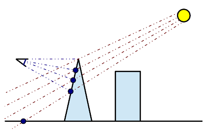
Occlusion rays from the light source

Occlusion rays are traced through the scene a light sources and a halton sequence is used to determine a random position and direction for the occlusion ray. The light source is selected using a cumulative distribution function based on the power of the light sources (stronger lights receive more photons). On each intersection excluding the first, an occlusion photon is generated. Figure 1 displays this approach:
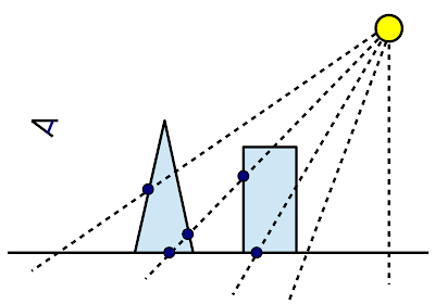
Figure 1: Light source sampling. Occlusion rays (striped lines) are shot from the light source.
Upon each intersection, except for the first intersection, an occlusion photon is stored.

Occlusion rays from the camera

Camera rays are traced randomly from the camera's viewpoint. The first intersection point of this ray will be used to determine the direction to shoot occlusion rays to. The origin of the occlusion ray is determined by selecting a random point on a light source. The light source is selected by the cumulative distribution function of the power of the light sources. This technique is displayed in figure 2:
Figure 2: Camera sampling. First camera rays (blue lines) are traced from the camera. Their
first intersection points are used to determine the direction of the occlusion rays (red lines).
The origin of the occlusion rays is determined by taking a point on a light source using
a cummulative distribution function. 


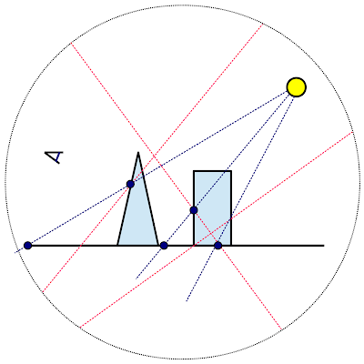
Uniform occlusion rays

With this technique we want the density of the occlusion photons to be evenly distributed through the scene. To accomplish this, I used global line sampling (since PBRT does not allow you to acces the geometry of the scene directly). With this technique, random rays are shot through the scene and each surface has a chance proportional to it's surface area to be hit.

First the bounding sphere of the scene is determined. Then two points are randomly generated on this sphere and a ray connecting these two points is shot through the scene.

One of the intersection points of these rays is randomly selected, and chosen to be the direction to shoot the occlusion rays to. The origin of the occlusion rays is determined as described in the previous subsection; by choosing a random point on a light source. 

This technique is shown in figure 3:
Figure 3: Uniform sampling. Random rays (red lines) are shot through the scene. One of their intersection
points is chosen and used as the direction to shoot occlusion rays (blue lines) to. The origin of the
occlusion rays is determined by choosing a random point on the light source.

Results

The images below show some of the results along with the used parameters and rendering times. All of the scenes were rendered on the following hardware: Intel Core i7 - 2630QM at 2.0 Ghz, 6GB of DDR3 running Ubuntu 12.04 (64-bit).

Comparison of the rendering techniques

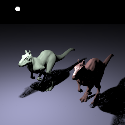
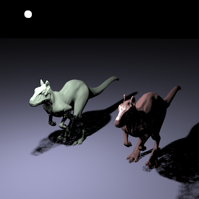
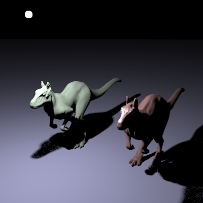
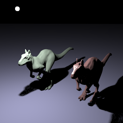
First I will compare the different techniques (occlusion mapping without light photons, occlusion mapping with light photons and the technique by Jensen) with each other. The results below are rendered with the three techniques and compared to a standard ray-traced image. The images show the killeroo scene that comes with PBRT, with 8 samples per pixel.

Rendering with 10,000 photons (light source radius 1)


Occlusion mapping without light photons.
Number of photons: 11903
Average number of occluders per photon: 1.90817
Occlusion shooting time: 0.118894s
Rendering time: 2.64184s
Total time: 2.76073s
Occlusion mapping with light photons.
Number of photons: 25912
Average number of occluders per photon: 0.231283
Occlusion shooting time: 0.094949s
Rendering time: 2.63185s
Total time: 2.7268s
Jensen's technique.
Number of photons: 25925
Average number of occluders per photon: 0.231514
Occlusion shooting time: 0.107828
Rendering time: 2.57188s
Total time: 2.67971s
Direct lighting.
Total time: 14.2238s

Rendering with 100,000 photons (light source radius 1)


Occlusion mapping without light photons.
Number of photons: 101844
Average number of occluders per photon: 1.89236
Occlusion shooting time: 0.768156s
Rendering time: 3.19457s
Total time: 3.96273s
Occlusion mapping with light photons.
Number of photons: 115409
Average number of occluders per photon: 0.225866
Occlusion shooting time: 0.188688s
Rendering time: 3.19719s
Total time: 3.38588s
Jensen's technique.
Number of photons: 115350
Average number of occluders per photon: 0.225626
Occlusion shooting time: 0.184848s
Rendering time: 2.87288s
Total time: 3.05773s
Direct lighting.
Total time: 14.2238s

Rendering with 1,000,000 photons (light source radius 1)


Occlusion mapping without light photons.
Number of photons: 1001683
Average number of occluders per photon: 1.8944
Occlusion shooting time: 8.53205s
Rendering time: 6.40291s
Total time: 14.9935s
Occlusion mapping with light photons.
Number of photons: 1015612
Average number of occluders per photon: 0.225866
Occlusion shooting time: 1.96708s
Rendering time: 6.92928s
Total time: 8.89636s
Jensen's technique.
Number of photons: 115350
Average number of occluders per photon: 0.225626
Occlusion shooting time: 1.95626s
Rendering time: 5.60054s
Total time: 7.55659s
Direct lighting.
Total time: 14.2238s

Rendering with 100,000 photons (light source radius 3)


Occlusion mapping without light photons.
Number of photons: 101675
Average number of occluders per photon: 1.89546
Occlusion shooting time: 0.786429s
Rendering time: 3.45047s
Total time: 4.2369s
Occlusion mapping with light photons.
Number of photons: 115387
Average number of occluders per photon: 0.227209
Occlusion shooting time: 0.187175s
Rendering time: 3.13611s
Total time: 3.32329s
Jensen's technique.
Number of photons: 115346
Average number of occluders per photon: 0.2269
Occlusion shooting time: 0.18869s
Rendering time: 2.96835s
Total time: 3.15704s
Direct lighting.
Total time: 14.6854s

Rendering with 1,000,000 photons (light source radius 3)


Occlusion mapping without light photons.
Number of photons: 1001686
Average number of occluders per photon: 1.89493
Occlusion shooting time: 8.58199s
Rendering time: 6.75203s
Total time: 15.334s
Occlusion mapping with light photons.
Number of photons: 115387
Average number of occluders per photon: 0.227209
Occlusion shooting time: 1.9558s
Rendering time: 7.1825s
Total time: 9.1383s
Jensen's technique.
Number of photons: 1014080
Average number of occluders per photon: 0.225214
Occlusion shooting time: 2.02617s
Rendering time: 5.78872s
Total time: 7.81489s
Direct lighting.
Total time: 14.6854s

The above sequence of images shows that for a large number of occlusion photons the results converges to the correct image. Furthermore we can make the following remarks about the three techniques:


  1. Occlusion mapping without light photons is best at preserving the shadow boundaries. The difficulty with this technique is that when a small number of occlusion photons is created, light dots are formed inside the shadow (will be discussed further)
  2. Occlusion mapping with light photons partially solves this problem. Thanks to the light photons, shadow rays will only be traced in the penumbra regions (the soft shadow regions), because light photons will never occur in regions which are fully in shadow. The problem with this technique is that there is less information about the occluders in the occlusion map (the average number of occluders per photons is only around 0.2 per photon).
  3. Jenssens technique is only added for comparing the other two techniques with a technique that does not trace any shadow rays. The ratio of light photons versus light and occlusion photons is only a rough estimate. To get exact results a prohibitive number of photons would need to be stored and the lookup radius for the occlusion map should nearly be zero.

Comparison of the occlusion shooting methods

Finally we compare the methods for distributing the occlusion photon in the scene. For this we render the killeroo scene with 100,000 and 1,000,000 occlusion photons (no light photons).

Rendering with 100,000 occlusion photons
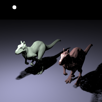
Light sampling
Average number of occluders per occlusion photon: 1.89528
Occlusion photon shooting time: 0.863877s
Render time: 3.36405s
Total time: 4.22793s
Camera sampling
Average number of occluders per occlusion photon: 2,14348
Occlusion photon shooting time: 0.504893s
Render time: 3.96897s
Total time: 4,47387s
Uniform sampling
Average number of occluders per occlusion photon: 1,87973
Occlusion photon shooting time: 25.7469s
Render time: 3.40524s
Total time: 29.1521s

Rendering with 1,000,000 occlusion photons
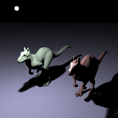
Light sampling
Average number of occluders per occlusion photon: 1,87973
Occlusion photon shooting time: 8,52909s
Render time: 6,69704s
Total time: 15,2261s
Camera sampling
Average number of occluders per occlusion photon: 2,14517
Occlusion photon shooting time: 3,59355s
Render time: 6,98851s
Total time: 10,5821s
Uniform sampling
Average number of occluders per occlusion photon: 1,87756
Occlusion photon shooting time: 298,16s
Render time: 6,97551
Total time: 305,135s

From the resulting images we can conclude that camera sampling is the most effective way. On average, more occlusion information is stored. Thanks to the camera driven construction of the occlusion map, we can be certain that occlusion photons are stored in visible locations. Finally we can see that the resulting images are better (compare the right flank of the right killeroo in the images).

Camera sampling is also more efficient in the time needed to construct the occlusion map. Light sampling wastes a lot of time shooting rays in directions that do not have any geometry. The global line sampling algorithm for uniform sampling also generates a lot of rays that do not intersect any geometry in the scene.


Conclusion

The current implementation still has some issues. The main issue that occurs are the light spots in the shadow regions, which can be seen in the figure below:
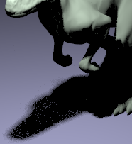
Light spots in the shadow regions
These light spots occur because some triangles in the mesh are never hit by any occlusion ray. This means that these triangles can never be tested for occlusion leading to false misses during rendering. This problem will become even more severe when the light sources are large.

A solution to this problem would be to create large volumetric occluders inside the models and to store these volumetric occluders inside the occlusion photons too. This will partially resolve the problem because altough occlusion rays may miss some small triangles, they are less likely to miss the larger volumetric occluders. The volumetric occluders can also be used to increase the performance. Since it is more likely that a volumetric occluder is hit than that a triangle of the mesh is hit (since volumetric occluders are usually large), we can choose to intersect the volumetric occluders first (which are cheaper to intersect).

Occlusion mapping with light photons also solves the problem of the light spots in the shadow regions.
No shadow rays will be shot from regions that are in full shadow because they can't contain any light photons. Therefore the false misses are avoided. The downside is that when light photons are used, less information about occlusion is stored in the occlusion map for the same number of photons. (without light photons, the average number of occluders per photon is 1.8; with light photons, the average number of occluders per photon is 0.2)

Finally, we could also store neighbouring triangles of an occluder in an occlusion photon. This could affect performance, since the number of stored occluders will increase by a great amount.
Monday, October 22, 2012

Exploring Occlusion Mapping

During my meeting with professor Dutré, we concluded that Occlusion Mapping could be a viable method for probabilistic visibility. In this blog post, I would like to elaborate a bit more on my thoughts of this technique. I will start by restating the idea, followed by a possible extension on it. I will conclude with some possible techniques to reduce memory usage and to increase performance.


Occlusion mapping

In a preprocessing step, occlusion photons are be shot from the light source. When these occlusion photons encounter their first intersection, nothing happens. However, on the second and on each subsequent intersection, an occlusion photon is created. An example of this process is shown in figure 1.
Figure 1: Occlusion photon shooting. Upon the first intersection, no photon is stored.
Only after the second and subsequent intersectons, occlusion photons are created. 
Each occlusion photon stores a list with the previously intersected occluders as shown in figure 2. This figure shows how occlusion photons are shot through a scene with 5 occluders and how the list of occluders is stored.
Figure 2: Occlusion photons are shot through a scene with 5 occluders and each
occlusion photon records the previously intersected occluders.
During the rendering pass, a lookup is done around the first intersection point of the camera ray. The occluders of the nearest photons are gathered and only they are used for shadow testing. When no occlusion photons are found, the point is said to be in light and no shadow rays are shot.


Occlusion mapping with light photons

Instead of only storing occlusion photons, we could also store light photons. Light photons are stored like regular photons. They are created only upon the first intersection. Figure 3 shows the same as figure 2, but extended with the light photons.

Figure 3: Shows the same scene as figure 2 but extended with light photons.


Light photons can be used to find areas that are completely in light and combined with the occlusion photons, they can be used to find areas that are completely in shadow. This is done in the following way.

During the rendering phase, a lookup is done around the first intersection point of a camera ray. The found photons can be either:
  • Only light photons: the point is completely in light and no shadow rays have to be traced.
  • Only occlusion photons: the point is completely in shadow and no shadow rays have to be traced.
  • A mix of light and occlusion photons: visibility is determined by sending shadow rays to all the occluders in the occlusion photons.
This scheme limits shadow ray casting to the soft shadowed regions.


Reducing the memory requirements

The memory requirements of this technique are very high. For accurate results, a large number of photons have to be traced through the scene. Furthermore, a unique occlusion map has to be created for every light source present in the scene. Finally, each occlusion photon stores a list of occluders, which requires a lot of memory, especially for scenes with a large depth complexity. Therefore, I propose a couple of methods to decrease the memory usage.

Sparse storage of occlusion photons

During the creation of the occlusion map, we will only sparsely store an occlusion photon. For this to work we assume the set of occluders locally doesn't change much. As long as we trace enough occlusion photons, the result will be the same. 

Figure 4 shows this approach. In the left figure, we see that all the occlusion photons are stored. On the right side of the figure, we randomly discarded half of the photons (the discarded photons are grayed out). Photons which are colored the same store the same set of occluders.

Figure 4: Sparse storage of occlusion photons. Occlusion photons have the same color
when they store the same set of occluders. The grayed photons in the right side are the
discarded photons.
The figure shows, if we perform a lookup in the occlusion map with a large enough search radius, we would get the same results.

Sparse storage of occluders

Instead of storing the complete list of occluders, we can also chose to store a limited set of occluders. The choice and the amount of occluders is still a question, there are several options:
  • only store the x previous occluders.
  • only store the x largest occluders
  • only store the x occluders closest to the light source
  • store the occluders which are not yet found in other photons in the area
  • ...
This will require some testing to see how the choice of occluders changes the result. There will not be one silver bullet, but it could be that for certain specific scenes, one choice of occluders will work great.

Linked storage of occlusion photons

For every occlusion photon, we could only store the previous intersected primitive and a reference to the previous photon. The full set of occluders can then be found by traversing the photons back into the direction of the light source. Figure 5 shows this approach to storing the set of occluders.
Figure 5: Storing the complete set of occluders by storing only one occluder
per occlusion photon and a reference to the previous occlusion photon.

Adaptive removal of occluders

Finally we could start with a complete set of occluders in each occlusion photon and maintain statistics. This allows us to remove occluders which have rarely been used.


Improving performance

To improve the performance of occlusion mapping we could use volumetric occluders. This approach would help in scenes with lots of detailed meshes. Instead of storing the reference to a small triangle, we could instead store the reference to a much larger volumetric occluder. This approach will help in a couple of ways:
  • less intersection tests
  • beter cache coherence
  • less photons are needed
We will need less intersection tests because volumetric occluders are large and nearby occlusion photons will probably hit the same volumetric occluder, which improves cache performance. We will also need less photons. 

To see why we need less photons you have to imagine a scene with a large model (e.g. the Stanford Dragon). In order to be sure that there are no holes in the shadow of the final image, each triangle should have at least one occlusion photon containing it. In other words, every triangle should be in the occluder list of at least one occlusion photon. If this is not the case, it could be possible that a triangle is not intersected with a shadow ray and thus leaves a hole in the shadow.
Using volumetric occluders elevates that problem.


Conclusion

There are still a lot of open questions on Occlusion Mapping. At the moment, memory is a bottleneck and the methods to reduce memory consumption need testing. Therefore it is time to start on a first implementation.

Saturday, October 20, 2012

More ideas on probabilistic visibility

Thursday I had my second meeting with professor DutrĂ©. As a preperation for this session I tried to come up with some additional ideas besides the Occlusion Mapping approach. Although some of them had great potential, we concluded that none of the other approaches were as versatile as occlusion mapping. Before I want to go deeper on the subject of occlusion mapping, I will first describe my other  ideas.

Lightbuffer with virtual point lights

In a preprocessing step, a number of virtual point lights (VPL's) would be distributed through the scene. In a next step, all the geometry would be projected upon a hemicube surrounding the VPL's as in figure 1.

Figure 1: Example of a projection on the hemicube
The light buffer would store all the geometry the overlapping geometry, not only the closest one. When shadow ray needs to be traced to the light source, it is intersected with the hemicube. This allows a quick retrieval of all the possible occluders. In the next step, probabilistic visibility can be used to only intersect one or two of the possible occluders.

The downside of this approach is that the preprocessing is computationally intensive. For every VPL we need to iterate six times over the geometry of the scene and unfortunately, the number of VPL's needs to be large to approach global illumination. Furthermore, memory consumption can be quite excessive if the resolution of the grid is high. If we would decide to keep the resolution low, artifacts can appear.

The upside would be that graphics hardware allows to project the geometry quickly on the cubes.

Reference: Eric A. Haines and Donald P. Greenberg. The Light Buffer: A Shadow-Testing Accelerator. Computer Graphics and Applications, IEEE Volume 6 p. 6-16, 1986.

Volumetric occluders

This approach was meant to be used on watertight models in the scene. First, a volumetric occluder is created for the watertight model. A volumetric occluder is a simple geometric object that tries to fill's a model as tight as possible.
Figure 2: Volumetic occluders for the Stanford Dragon
Image courtesy: Peter Djeu, Sean Keely, Warren Hunt. Accelerating Shadow Rays Using Volumetric Occluders and Modified kD-tree traversal. 2009. 

Now we would use probabilistic visiblity to either intersect the model or the volumetric occluder in the following way:
The chances could be set in the following manner:
These chances will favor the occluder when it fits the model tightly. The term pintersect should be as low as possible, but is still needed to avoid bias in the Monte Carlo Estimate.

This method would accelerate tracing shadows because intersecting the volumetric occluder is cheaper than intersecting the model.

It is not yet clear whether this method could work. We are essentially adding more geometry to the scene and this could create a bias.

Reference: Peter Djeu, Sean Keely, Warren Hunt, 2009. Accelerating Shadow Rays Using Volumetric Occluders and Modified kD-tree traversal. High Performance Graphics 2009 p. 69-76

Thursday, October 4, 2012

Paper summary - continued

The following papers describe some more algorithms that could be combined with probabilistic visibility. The first algorithm reduces the number of shadow rays that need to be traced. The second paper describes a novel representation for the Bounding Volume Hierarchy (BVH) that uses 0 bytes of memory. The third also describes a compact representation of the BVH that maintains a comparable performance.

The final summarized paper uses advanced caching strategies and an interesting combination of Instant Global Illumination and Instant Radiosity to exploit spatial coherence. Furthermore it reuses the cache between frames to achieve temporal coherence. Especially this paper looks very interesting to me, since we can use the cache to make valid guesses about the probabilities in probabilistic visibility.

Adaptive Shadow Testing for Ray-tracing

This paper presents a method to reduce the number of shadow rays by testing the most important light sources first and quit testing the remainder of the lights which have a low contribution. This approach trades accuracy for speed.

During rendering a global statistic is build up in the scene that keeps track of the number of hits versus the number of shadow ray tests for each light source. This statistic is used to discard unimportant light sources that have been invisible most of the time.

The only incurred memory overhead is some extra integers per light source to keep track of the number of hits versus the number of tests. 

However for each shadow ray, the potential contributions from all the light sources have to be calculated, in order to know which ones will have a higher contribution.

Reference: Greg Ward. Adaptive shadow testing for ray tracing. In Photorealistic Rendering in Computer Graphics (Proceedings of the Second Eurographics Workshop on Rendering, pages 11–20. Springer Verlag, New York, 1994.

Implicit Object Space Partitioning: The No-Memory BVH

The authors present a new algorithm that allows a BVH to be represented implicitly. The main observation is that the geometry defines the BVH. The BVH is represented by ordering the list of the triangles of the scene. From this ordering, the bounding planes are reconstructed during the traversal of a ray.

Construction is top-down, switching between the axes in round-robin fashion (xyzxyz...). The hierarchy is represented as a complete, left-balanced, binary tree ordered in breath-first order. This allows to index the list with triangles as a heap (hereby saving explicit storage of pointers).

During traversal, the bounding planes are reconstructed from the two triangles that represent the current node in the hierarchy.

The result is that this representation requires no memory at all (except for a list with all the geometry of the scene). However there is a slight performance decrease compared to state of the art BVH's. This drawback can be alleviated partially by using a real BVH structure for the top levels, and by representing the nodes of that tree by No-Memory BVH's.

Being able to create an acceleration structure using 0 bytes of memory can be quite important, since an acceleration structure usually takes up a lot of space. For large scenes, this could mean that the acceleration structure would not fit into main memory, decreasing performance dramatically because of slow disk IO.

Reference: M. Eisemann, P. Bauszat, S. Guthe, M. Magnor, 2012. Geometry Presorting for Implicit Object Space Partitioning. Eurographics Symposium On Rendering 2012, Volume 31, Number 4

Ray Tracing with the Single Slab Hierarchy

By noting that a child of a BVH node shares a lot of planes with its parent. Therefore, the authors propose a BVH hierarchy that only uses one bounding plane. Similar to BVH, the hierarchy is traversed in a top-down fashion and complete subtrees can be skipped if a ray misses a node.

Construction is almost identical to a regular BVH. This time two splitting planes will be chosen (preferably using different axis to get tighter bounds). Any construction technique can be used (e.g. SAH, spacial median cut,...).

Traversal resembles BVH traversal, but with the complexity of kD-tree traversal. In each step, the active ray interval is maintained and updated. Nodes outside this interval can be skipped.

The results from the implementation show that this BVH algorithm is comparable in speed (and sometimes even faster) than state of the art implementations. Furthermore, the Single Slab Hierarchy (SSH) requires only 25% of the memory of a complete BVH. The tests show that the number of node traversals is twice as high as with regular BVH's. This is not much of a problem since the intersection tests for nodes in the SSH are six times less expensive. Also the slabs do not fit the geometry as tightly compared to regular BVH's, which slows down rendering. The results indicate however that only one extra primitive needs to be intersected per ray.

Reference: M. Eisemann et al, 2011. Ray Tracing with the Single Slab Hierarchy.

Instant Caching for Interactive Global Illumination

This paper proposes an interesting combination of irradiance caching and instant radiosity to accelerate the global illumination computation. Furthermore, they exploit temporal coherence in animations by identifying the cached calculations that are invalid due to movement of geometry. This allows to achieve great improvements in animations.

The algorithm starts by shooting photons from the light sources to create the Virtual Point Lights (VPL's) and subsequently performs a gathering pass. In the gathering pass, the irradiance from the VPL's is evaluated at a sparse set of points (in contrast to the Irradiance Cache in which the complete hemisphere is sampled). Computation of the indirect diffuse component however is similar to the Irradiance Cache.

Further performance is gained in animations by reusing the cached samples. At each frame the samples have to be checked whether they have become invalid. Five cases are identified for a cached sample:

  1. VPL is occluded by moving object
  2. VPL is deoccluded by moving object
  3. Cached sample is occluded by moving object
  4. Cached sample is deoccluded by moving object
  5. Sample/VPL is on a moving object
At the start of each frame the VPL's are retraced, solving case 1 and 2. Case 3 is solved by tracing rays from the cached samples towards the light sources and only intersecting the moved objects (a cheap acceleration structure could be built over those objects).
For case 4, all objects of the scene should be intersected again. However, we only have to do this when the occluder of the sample is a dynamic object. For case 5 the sample simply has to be discarded.

The results show an average 2x speedup when compared to Instant Global Illumination (IGI) in static scenes and a 4x speedup in dynamic scenes. This speedup is the result of stronger spatial and temporal coherence.

The resulting images are also validated with a perceptual metric. For this they use the HDR-VDP metric, which visualizes the areas that humans are most likely to be detect as different. Compared to IGI, the difference is never larger than 0.33%. This shows that there is no tradeoff in quality for the speedup. Comparison against ground truth path traced images shows that the error is never larger than 2,11%.

Reference: K. Debattista et al. 2009. Instant Caching for Interactive Global Illumination. Computer Graphics Forum Volume 28 (2009), number 8 pp. 2216-2228.